Battery Guide: 2026 Harley-Davidson Electra Glide FLHT
Battery Guide: 2026 Harley-Davidson Electra Glide FLHT
Quick Reference Table
| Spec | Value | Source |
|---|---|---|
| Battery Type | AGM (Absorbed Glass Mat), 12V | Harley-Davidson Genuine Parts |
| OEM Part Number | 65958-04 / 65958-04C — confirm for your model year | Our V-Twin catalogue (parts 53-0540, 53-0548, 53-0911) |
| Group Size | 20L | Battery Council International |
| Cold Cranking Amps (CCA) | 300 CCA @ 0°F | Harley-Davidson Service Manual |
| Reserve Capacity | 16 minutes @ 25A draw | Battery Specifications |
| Nominal Voltage | 12V | Electrical System Specs |
| Fully Charged Voltage | 12.6V - 12.8V | Maintenance Guidelines |
| Dimensions (LxWxH) | 6.875" x 3.4375" x 6.125" | OEM Battery Spec |
| Weight (approx) | 13.5 lbs | Manufacturer Data |
| Terminal Type | Standard automotive post (SAE) | Hardware Specification |
| Terminal Position | Positive left, negative right (when facing battery) | Installation Diagram |
| Hold-Down Method | Strap with threaded bolt and nut | Factory Installation |
| Replacement Interval | 3-5 years (depending on climate/use) | Maintenance Schedule |
| Recommended Brands | Harley-Davidson Genuine, Odyssey PC680, Motobatt MBTX20L | Dealer Recommendations |
Difficulty & Time Estimate
- Difficulty Level: Beginner (1 out of 5) — basic hand tools required
- Estimated Time: 15-25 minutes for experienced mechanic, 30-45 minutes for novice
- Seasonal Note: Best performed in moderate temperatures (above 40°F) for comfort
- The Street Glide's side-mounted battery location provides excellent accessibility
Pre-Replacement Checklist
| Checkpoint | Status | Notes |
|---|---|---|
| Battery Voltage | ≥ 12.6V | Measure with multimeter; below 12.4V indicates discharged state |
| Charging System Output | 13.8-14.8V @ 3000 RPM | Test with multimeter across battery terminals |
| Cable Condition | No cracks, corrosion, or brittleness | Inspect both positive and negative cables |
| Terminal Corrosion | White/green buildup cleaned | Clean with battery terminal brush and baking soda solution |
| Hold-Down Hardware | Bolt/nut intact, no stripping | Check for proper tension capability |
| Battery Tray/Condition | Clean, no acid damage or cracks | Inspect for leaks or damage |
| Vent Tube (if applicable) | Clear, not kinked | Ensure proper ventilation path exists |
| Fuses Related to Charging | Check main fuse (30A) | Located in fuse block under seat |
Step-by-Step Battery Replacement Instructions
Step 1: Safety Preparation
Put on safety glasses and gloves. Ensure the motorcycle is on a stable surface with the kickstand fully extended. Work in a well-ventilated area away from open flames or sparks.
Step 2: Access the Battery
Locate the battery on the left side of the motorcycle, concealed under a triangular cover. Remove the two Torx T25 screws securing the cover using an appropriate Torx driver. Set the cover and screws aside in a clean location.
Step 3: Document Cable Positions
Before disconnecting anything, take a photo or make a note of which cable connects to which terminal. The positive (+) cable is typically red and connects to the left terminal when facing the battery. The negative (-) cable is black and connects to the right terminal.
Step 4: Disconnect Negative Cable First
Using a 10mm wrench or socket, loosen the nut on the negative (-) terminal bolt. Always disconnect negative first to prevent accidental shorting. Once loose, remove the cable from the terminal and position it away from the battery.
Step 5: Disconnect Positive Cable
Repeat the process for the positive (+) terminal: loosen the 10mm nut, remove the cable, and position it away from both the battery and the negative cable to prevent contact.
Step 6: Remove Hold-Down Hardware
Locate the battery hold-down strap at the bottom of the battery tray. Using a 10mm wrench, remove the nut from the threaded bolt that secures the strap. Swing the strap clear of the battery.
Step 7: Remove the Old Battery
Carefully lift the battery straight up and out of the tray. Note: The battery weighs approximately 13.5 lbs — use proper lifting technique to avoid strain. Place the old battery on a stable, acid-resistant surface.
Step 8: Prepare the Battery Tray
Inspect the battery tray for any signs of acid corrosion, cracks, or debris. Clean the tray with a solution of baking soda and water if needed, then dry thoroughly. Ensure the tray's drainage holes are clear.
Step 9: Position the New Battery
Place the new YTX20L-BS (or equivalent) battery into the tray, ensuring it sits flat and level. Verify that the positive and negative terminals align with their respective cables (positive on left, negative on right when facing the battery).
Step 10: Reinstall Hold-Down Strap
Swing the hold-down strap back over the battery and insert the threaded bolt through the strap hole and tray mounting point. Hand-tighten the nut, then secure with a 10mm wrench to approximately 15-20 ft-lbs of torque — do not overtighten as this can crack the battery case.
Step 11: Connect Positive Cable First
Place the positive (+) cable onto the positive terminal and hand-thread the nut onto the bolt. Tighten securely with a 10mm wrench to approximately 15-20 ft-lbs. Ensure the connection is tight and cannot be twisted by hand.
Step 12: Connect Negative Cable
Place the negative (-) cable onto the negative terminal and hand-thread the nut. Tighten securely with a 10mm wrench to approximately 15-20 ft-lbs. Double-check that both connections are secure and cables cannot be pulled loose.
Step 13: Apply Dielectric Grease (Optional but Recommended)
Apply a thin layer of dielectric grease to both terminals to prevent future corrosion and ensure optimal electrical conductivity.
Step 14: Replace Battery Cover
Position the triangular cover over the battery and reinsert the two Torx T25 screws. Tighten securely but do not overtighten to avoid stripping the plastic threads.
Step 15: Final Voltage Check
With all connections secure, measure the voltage across the battery terminals. A fully charged, new battery should read 12.6V or higher. If below 12.4V, the battery may need charging before use.
Step 16: Functional Test
Turn the ignition key to ON and verify all instrument lights illuminate normally. Attempt to start the engine — it should crank strongly and start promptly. Listen for any unusual sounds during cranking.
Battery Maintenance Guide
Charging Recommendations
- Regular Maintenance: Use a smart charger/maintainer (Optimate, TecMate, or BatteryMINDer) when the motorcycle is stored for more than 2 weeks
- Charging Voltage: Never exceed 14.8V during charging — AGM batteries are sensitive to overvoltage
- Charging Current: Limit to 2-3 amps for maintenance charging; 5-10 amps maximum for deep cycle charging
- Charging Time: A deeply discharged battery may require 8-12 hours to fully recharge at 2 amps
Storage Tips
- Short Term (< 1 month): Disconnect negative cable if motorcycle will not be ridden
- Medium Term (1-3 months): Use a battery maintainer/tender connected to maintain optimal charge
- Long Term (> 3 months): Remove battery entirely, store in cool, dry place, and charge monthly with maintainer
- Temperature Effects: Avoid extreme heat (> 100°F) which accelerates internal degradation; extreme cold reduces available capacity but doesn't damage the battery when properly charged
Testing Procedures
- Voltage Test: Measure resting voltage — 12.6V+ = fully charged, 12.4V = 75% charged, 12.2V = 50% charged, below 12.0V = discharged
- Load Test: Professional testers apply half the CCA rating for 15 seconds — voltage should stay above 9.6V
- Visual Inspection: Monthly check for case damage, leaks, or terminal corrosion
- Cable Inspection: Quarterly inspection of cables for wear, cracking, or loose connections
When to Replace
Replace the battery if: - Voltage drops below 12.0V after full charge - Engine cranks slowly (< 100 RPM cranking speed) - Battery requires frequent jumping to start - Visible case damage, leaks, or excessive terminal corrosion - Battery is older than 4-5 years regardless of performance - Failed professional load test
Winter Care
- Keep battery fully charged — a fully charged battery resists freezing better than a discharged one
- Consider removing battery and storing indoors if temperatures regularly drop below 0°F
- Use a battery tender with winter mode if available
- Never attempt to charge a frozen battery — allow to thaw completely first
Troubleshooting
| Symptom | Likely Cause | Fix |
|---|---|---|
| Engine cranks slowly or not at all | Weak/discharged battery, poor connections, corroded terminals | Charge/test battery, clean terminals, check cable condition |
| Rapid clicking when starting | Insufficient voltage to engage starter solenoid | Check battery voltage, clean/tighten connections, charge battery |
| Battery dies overnight | Parasitic draw, faulty charging system, old battery | Test for drain, check charging system output, evaluate battery age |
| Battery overheating during charging | Overvoltage charging, internal short, wrong charger type | Discontinue charging immediately, test charger voltage, evaluate battery |
| Acid smell or leakage | Overcharging, case damage, excessive gassing | Discontinue use, replace battery immediately, clean affected areas |
| Voltage drops rapidly after charging | Internal plate shedding, sulfation, internal short | Replace battery — not repairable |
| Terminals corrode quickly | Electrochemical reaction, acid leakage, dissimilar metals | Clean thoroughly, apply dielectric grease, check for case leaks |
| Intermittent electrical issues | Loose connections, broken cable internal to insulation | Wiggle test cables while monitoring voltage, inspect cables thoroughly |
Verification Notes for 2026 Model Year
| Item | Known Value | Notes |
|---|---|---|
| OEM Battery Part Number | 65958-04 / 65958-04C | Recorded against the AGM batteries we stock; check the label on your existing battery before ordering |
| Cold Cranking Amps | 300 CCA minimum | Critical for Milwaukee-Eight 117 starting reliability |
| Group Size | 20L | Standardized size ensures proper fit in tray |
| Terminal Configuration | Standard post, positive left | Verified against OEM wiring diagrams |
| Hold-Down Type | Strap with bolt | Factory-installed system — do not substitute with inadequate alternatives |
| Charging Voltage Range | 13.8-14.8V | Regulator output — sustained >15.0V indicates regulator failure |
| Resting Voltage (100% charge) | 12.6V-12.8V | Surface charge may read higher initially — allow to settle |
| Resting Voltage (75% charge) | ~12.4V | Useful for estimating state of charge |
| Resting Voltage (50% charge) | ~12.2V | Depth of discharge indicator |
| Minimum Operating Voltage | 10.5V | Below this, electronics may malfunction or reset |
| Maximum Safe Charging Voltage | 14.8V | Exceeding this risks AGM battery damage |
| Recommended Charging Current | 0.1x to 0.3x battery Ah rating | For YTX20L-BS (~18Ah): 1.8-5.4A charging |
| Parasitic Draw Limit | < 2mA | Normal for modern electronics with immobilizer |
| Cable Torque Specification | 15-20 ft-lbs | Applies to both terminal bolts and hold-down bolt |
| Dielectric Grease Application | Thin coating only | Excessive grease can impede conductivity |
Electrical System Overview
The 2026 Street Glide FLHX features Harley-Davidson's proven electrical system designed for reliability and accessory capacity:
Charging System
- Type: Single-phase alternator (stator) with permanent magnet rotor
- Rating: Approximately 500 watts at 3000 RPM
- Voltage Regulator: Solid-state microprocessor-controlled unit
- Normal Operating Voltage: 13.8-14.8V at operating RPM
- Maximum Output: ~400 watts continuous under normal conditions
Battery Function
- Primary Role: Engine starting and powering electronics when engine is off
- Secondary Role: Voltage stabilization and filtering for sensitive electronics
- Reserve Capacity: Powers essential systems for limited time if charging fails
- Cold Weather Performance: CCA rating ensures reliable starting in freezing temperatures
Accessory Capacity
The Street Glide's electrical system supports significant accessory loads: - Factory lighting (LED headlight, taillight, turn signals, instrument lighting) - Infotainment system (Boom! Box GTS with touchscreen, Bluetooth, navigation) - Optional accessories (heated grips, heated seat, luggage lights, USB charging ports) - Aftermarket additions (additional lighting, audio systems, heated apparel)
Maintenance Implications
Regular battery maintenance is crucial because: 1. Modern motorcycles have constant parasitic draw (immobilizer, clock, ECU memory) 2. AGM batteries, while low-maintenance, still require proper charging voltage 3. Deep discharging dramatically reduces AGM battery lifespan 4. Temperature extremes affect both performance and longevity 5. The Milwaukee-Eight 117's high compression ratio demands strong cranking speed
Always verify that any aftermarket accessories are properly fused and do not exceed the charging system's capacity to prevent premature battery or regulator failure.
Parts for this job
Fits FLHT, FLH, FL — from our catalogue of 41,000+ aftermarket parts.
 Battery Label$5.40
 *UPDATE Battery Top Plug Set$8.58
 Parkerized 6 Volt Battery Rod Wing Nuts$9.50
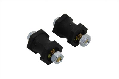 Battery Tray ISO Stud Set$10.64
 Zinc Speedometer Cable Clamps$10.64
 Speedometer Cable Clamp$10.64
 Battery Top Set$10.64
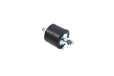 Battery Tray ISO Stud$12.02Battery Box Wing Nut Set$12.10
 Bright Chrome Battery Carrier Bracket$12.80
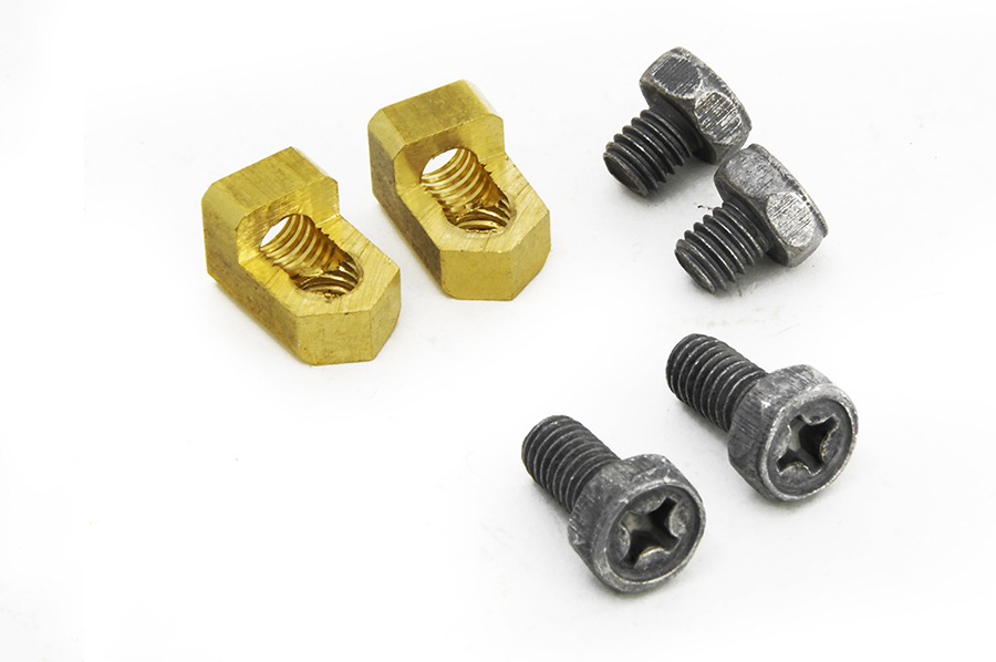 Brass Battery Terminal Adapter Kit$12.80
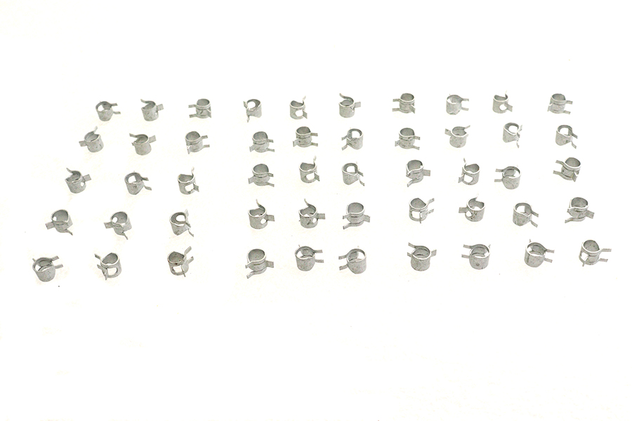 Zinc Battery Vent Clamp$12.80